Stage Light Controller
Jack Brzozowski (jtb237) and Kyle Infantino (ki88)
December 6, 2022
Objective
The goal of this project is to use a Raspberry Pi microcontroller to control stage lights using the DMX512 protocol. This would allow a small and inexpensive Raspberry Pi to replace the large and costly light controller boards that are typically used for this application.
Demonstration Video
Short video containing an overview of the design followed by a show illustrating some of the features of the light and a sample light show for "Nutshell" by Alice in Chains.
Introduction
This project was an effort to simplify and streamline the control of a stage light using the DMX512 protocol. The DMX512 protocol was invented by the Entertainment Services and Technology Association (ESTA) in 1988. The typical setup for producers setting up a light show involves getting a DMX controller, which is a board full of sliders and buttons larger than a typical laptop. These bulky controllers are cumbersome (and in our opinion, unnecessary) so our goal was to eliminate the need for them entirely by implementing the DMX controller by bit-banging GPIO signals. Ultimately, this means that we can replace the typical system with a Raspberry Pi connected to an XLR cable using two GPIO pins. While coming up with a solution that met the timing constraints of the protocol proved challenging, ultimately we successfully created an API capable of running light shows using a Raspberry Pi, and created a robust system that can reliably send packets to fixtures using DMX.
Target Device/System Architecture
For this project, we used two Betopper LS10 stage light fixtures, pictured below. These fixtures are 9 channel devices, where each channel allows us to control a different aspect of the light, such as its x position, y position, brightness, or color. While it is possible to control the lights independently, for the purposes of this project, we simply daisy chain the two together such that they both perform the same actions.
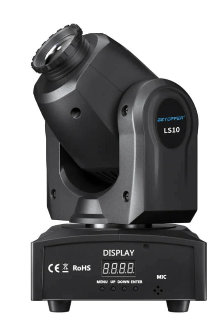
Betopper LS10 Stage Light
Given the functionality described above, we can achieve this in hardware using a modified XLR cable that connects to our new Raspberry Pi controller, which at the other end connects to the light fixture input. The light fixture also has an output port where we can use a standard XLR cable to connect the two lights together.
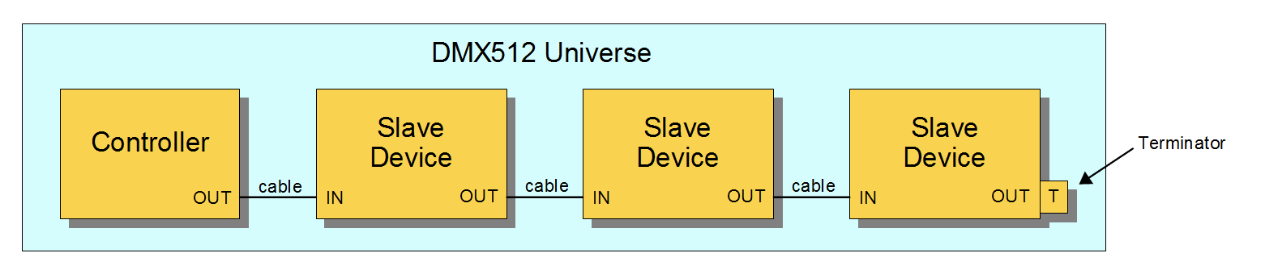
Example DMX Universe with Multiple Slave Devices
DMX512 Protocol
The DMX512 (or just DMX) protocol is the driving force behind this entire project. The stage light mentioned above, but also many others used in theatrical or musical applications, adhere to this protocol. In theory, this protocol is easy to understand. Whenever the line is idle, a logical 1 should be written to the data bus. To initiate a DMX frame, a “break” condition is applied in which the line is pulled low for a minimum of 92us. To be safe, we implement the break condition to be 100us. The break condition must be followed by a Mark After Break (MAB) which pulls the line high for at least 12us, but we implement this as 14us. After this, the DMX frame begins. A DMX frame consists of one NULL START code, which is 9 zeros, followed by two stop bits. From there, a maximum of 512 data bytes can be sent to all of the fixtures connected to this controller. This grouping of fixtures in an enclosed system with one controller is known as a “DMX universe.” Each byte is prefixed with one low start bit, and post-fixed with two high stop bits. The baud rate of the protocol is 250 kbits per second, meaning that each bit lasts 4us. This portion of the protocol looks a lot like serial UART communication with a baud rate of 250 kbits per second. Unfortunately, the break and MAB make it impossible to use a standard UART bus to control the fixture.
Each byte of data in a DMX Frame is referred to as a “channel.” Each fixture in the DMX universe can configure itself to have a starting address between 0 and 512, which indicates which channel it begins listening to. In the case of our target device, if the address is set to 1, the light will listen to the first 9 bytes of data after the null start code, but if the address is 9, it will ignore bytes 1-8 and listen to bytes 9-17. This allows us to independently control fixtures with the very same packet. However, this also means that we need to send redundant light commands to fixtures that should not move to avoid telling that light to do something undesirable. For example, if one light is supposed to be stationary, but another is supposed to begin some animation, we need to reconfirm to the first light that it should maintain its current position, its current brightness, etc.
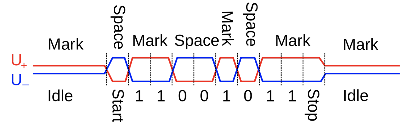
Waveform of DMX Protocol
The physical layer of the DMX protocol adheres to the RS-485 physical layer parameters. This ultimately means that the logical values are represented by a differential voltage between a data pair called Data+ and Data-. A logical zero is represented by Data+ being pulled low, and Data- being pulled high, resulting in -3.3V across D+/D-. A logical 1 is just the opposite. For this reason, we can use two GPIO signals without any ground connection to the Raspberry Pi to toggle the data lines. This makes interfacing with devices extremely easy and simple, which is really great when playing different venues that require transporting and setting up equipment over and over again.
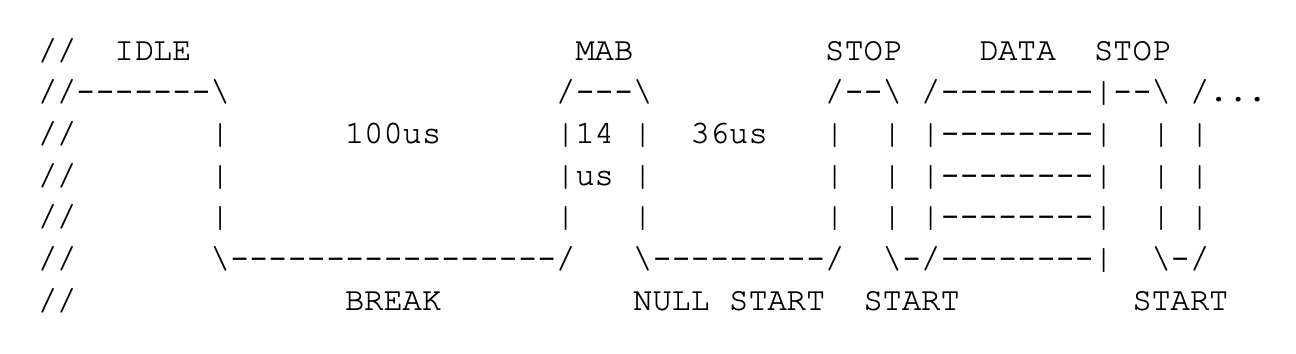
Timing Diagram of DMX Protocol
Design and Testing
Hardware Setup
In order to properly send packets to the light, we needed to connect to the light’s XLR port. Obviously, the RasPi does not possess an XLR port of its own, so in order to connect properly to the RasPi, we modified an XLR cable at one end, cutting off the connector to expose the data lines. We soldered solid core wire to the frayed copper to make it easier to plug into a jumper cable, and used heat shrink around each connection to ensure they wouldn’t short. A larger piece of heat shrink holds everything firmly in place and makes the hardware setup relatively clean. Each GPIO is connected to the light through a 220 ohm resistor to match the parameters of the RS-485 standard.
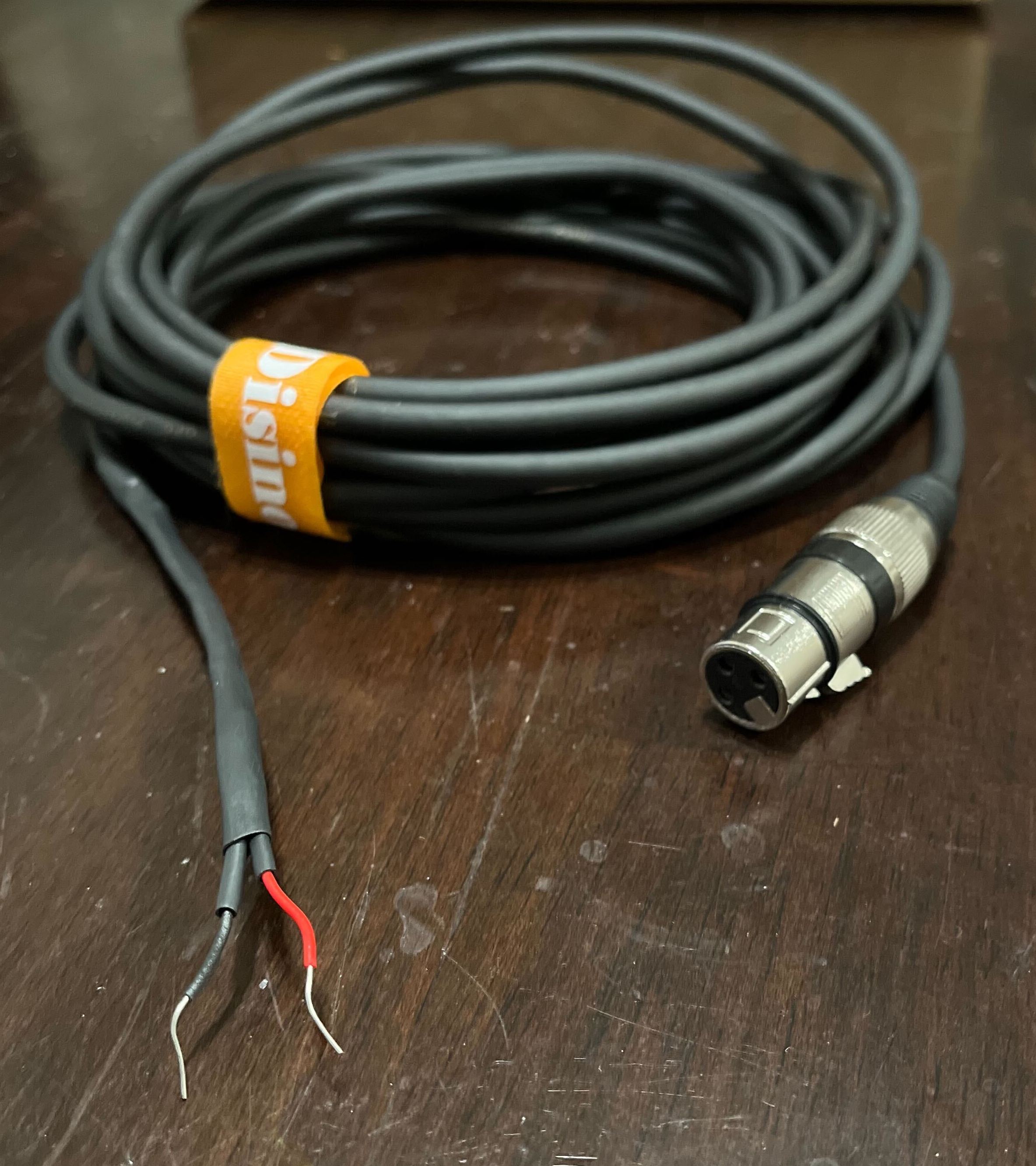
Modified XLR to USB Cable
Sending a DMX Packet in C
To ensure we could successfully send any packet over DMX, we first attempted to create a simple script to move the light. Our original plan was to use a USB to XLR wire to communicate with the light from the Raspberry Pi. However, after investigation into multiple Python libraries, we decided implementing the DMX protocol over USB was not feasible. We instead pivoted to using the GPIO pins to bit-bang the protocol. We used the PiGPIO C library to configure the desired GPIO pins and write the output. Since DMX requires a differential voltage between two wires, each wire was connected to a different GPIO pin.
The main issue with the GPIO approach is that DMX is a time-based protocol and requires that each data bit lasts exactly 4 microseconds. The timing of a typical program running on the Debian kernel is much too imprecise for this application. In order to make the timing more consistent, we needed to go through a series of improvements to our design. We used the PreemptRT kernel patch and gave our process a higher priority of 51 to start off. This ensured our process would not be preempted by lower priority processes. To verify the functionality of this solution, we generated a square wave on the Raspberry Pi and viewed it on an oscilloscope. The square wave generated using this setup would achieve 4 microsecond pulses most of the time, but it did not reliably transition at a perfect 4us every time. As it turns out, this was close enough to begin testing with the actual stage light, and send some successful commands to the light.
In order to adhere to the DMX protocol, we had to accurately model the behavior of the idle state, break, mark after break, and null start code, as well as the start bit, data, and stop bits for each data byte. In order to manage the timing of the protocol, we created a “wait” function that simply stalls for some number of microseconds based on the clock frequency of the RaspPi. To implement each step of the protocol, we write the correct value to the GPIO pins and wait for the amount of time defined above. For the initial testing of the design, we used hard coded data packets to minimize potential sources of error.
Creating a Light Control Library
Once we got simple, hard coded commands working on the stage light, we moved on to creating an easy-to-use library to control the light. Since the light has 9 channels to control different features of the light, we created an array of size 9 with each entry corresponding to a different channel. We then created human readable functions such as “set_xpos” to set the x position of the light or “set_color” to change the color of the light. These functions take in an integer 0-255 and write this value to the array index corresponding to that feature. The mapping of integer values to different light behavior for each feature is specified in the LS10 user manual. For example, a value of 10 in the color channel turns the light red, while a value of 30 turns the light blue. To eliminate the need for constantly consulting the user manual while programming the lights, we included mappings in the form of #define’s of each feature option to their corresponding integer. Once the user has modified the desired features, they call the “send_frame” function. This function sends each value of the array over the GPIO lines in accordance with the DMX protocol.
After creating a basic library for controlling the light, we moved to adding more advanced multi-command functions such as drawing a line or a circle. The draw_line function takes in arguments such as starting and ending x and y angles as well as the speed the light should move. The function then handles orienting the light to the correct starting position and moving it to the ending coordinates. The draw_circle function takes in a circle radius (in degrees) and a movement speed. Since the light only has a 540 degree range of horizontal motion, the function uses the current x position of the light to calculate which direction it should turn in order to achieve a full 360 degree rotation. Since each of these functions do not overwrite other indices in the send array, other desired features for the shape such as light color, gobo, and strobe can be set before calling the function.
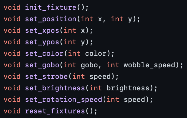
Some of the API functions used to control the light
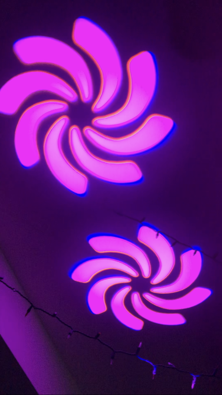
Daisychained Lights Showing Pink Spiral Gobo
Improving Stage Light Consistency
The creation of the light control library increased the programmability of the lights, however, we found the error rate of sending commands over GPIO was a significant barrier to using the lights. In terms of performance, this significantly diminished the impact of the performance the lights were attempting to display. For example, a smooth orange spin might suddenly turn into a strobing green shaking back and forth if a packet was misinterpreted. This would make the library effectively unusable for any real application. While the PreemptRT kernel patch and higher priority provided enough precision to send packets, the occasionally inconsistent timing still resulted in a frustratingly large number of these errors. In another effort to minimize disruption of the process, we decided to give the process its own exclusive core. To do this, we first isolated core 2 by adding the “isolcpus=2” command to /boot/cmdline.txt. We then ran the process on core 2 by prefacing the executable with “taskset -c 2”. While a designated core did somewhat reduce the error rate, it was still too high for real-world use.
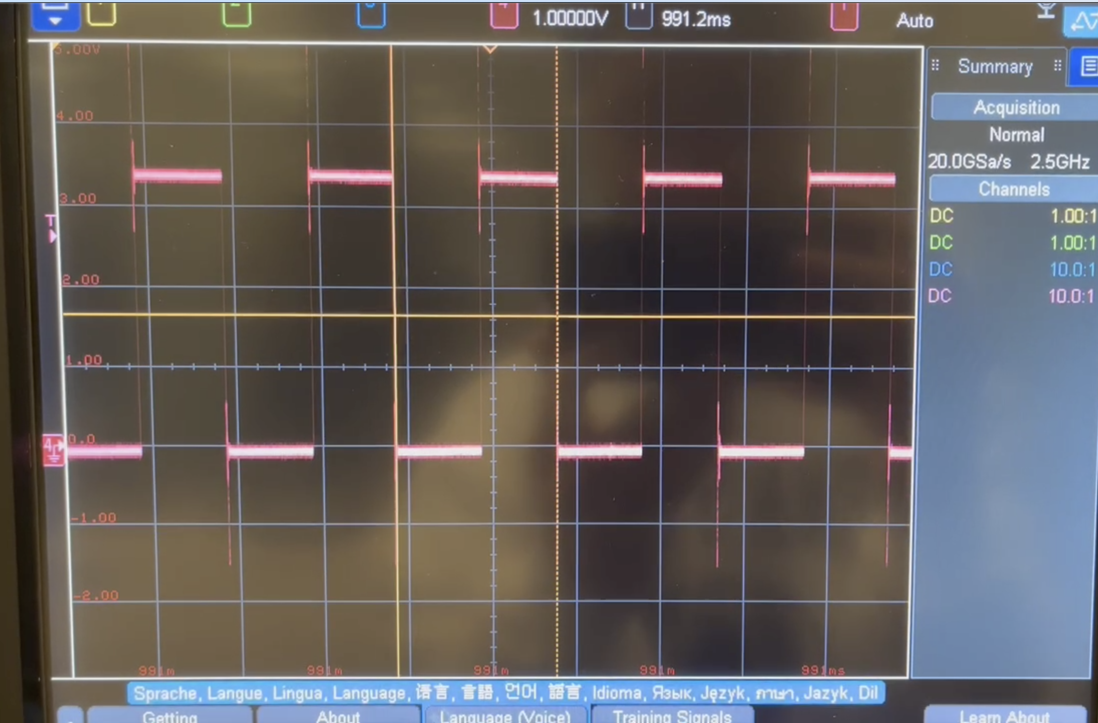
Waveform of 4us square wave with PreemptRT kernel patch. Each transition is not exactly 4us apart, indicating possible transmission errors.
One idea that we came up with to reduce the visibility of misinterpreted packets was to send packets over and over again every 2ms. The idea behind this is that the error rate we were seeing was roughly 10% by inspection, so 90% of the time the light would be told to do the right thing. For only 2ms, the light may flicker or jitter a bit if some bits are misinterpreted. In practice, this idea did indeed make the light show look a bit better, but there was still clear visible shaking and small flickers that made it look like the light was burning out. We knew this idea still wasn’t where we wanted to be.
The final optimization we implemented to reduce the error rate was the use of hardware PWM. This feature is included as part of the PiGPIO library and allows for data to be directly sent over GPIO lines using DMA. This is done through the use of a coprocessor, meaning the timing of the transmission cannot be disrupted by the linux operating system. What this boils down to is that the waveforms become far more precise in time. Given that DMX has no error checking or clock, this is crucial. All the interfacing with the PiGPIO library was done in the send_frame function, allowing the implementation details of the library to be abstracted away from the rest of our movement library. To implement DMX using the PiGPIO library, we created a “generic” waveform with 94 pulses. Each pulse included an attribute for which GPIO lines should be turned on during that pulse, which GPIO lines should be turned off during the pulse, and how long the pulse should last. Since the DMX protocol uses a differential voltage between two GPIO pins, each pulse would turn on one of the two pins and turn off the other pin. For example, to write a 0, the D+ pin would be turned on and the D- pin would be turned off. The first four of these pulses were used for the break, mark after break, null start, and stop bits. The other 90 pulses were for the 9 frames, with 10 pulses per frame. In each frame, the first pulse was used for the start bit, the next 8 pulses were used for data, and the last pulse was used for the stop bits. Since the length of each pulse could be set independently, a new pulse would only need to be added whenever the data lines changed. For example, instead of adding a new pulse for every 4 microseconds of the break, we could add one pulse with a length of 100 microseconds. We add a generic waveform with the correct number of pulses using the gpioWaveAddGeneric() function. Once the waveform is created, we send the waveform once over the GPIO pins.
The move to hardware PWM within the PiGPIO library allowed us to get extremely reliable packets. Another consideration that needs to be taken into account in music is staying in time with the song. Since this program will be run unsupervised (i.e. it will be executed and run from start to finish) it is really important to be able to accurately measure delays such that the program stays in time. We found that our busy-wait functions were not precise enough for these musical applications. Additionally, they simply busy-waited for some time, but did not consider any other computation time, and therefore would slowly drift further and further out of time. In order to remedy this, we decided to use linux’s “CLOCK_MONOTONIC” to determine when to send packets. Let’s suppose we wanted to be able to send one packet per second. We implement this using two different timestamps represented using the struct timespec data type. One of these timestamps is set by the send_frame() function right before it sends the break condition of the DMX frame. This timestamp is called last_frame, and indicates when the previous frame was sent. We create another timestamp called elig_time, which refers to the time at which packets will be eligible to be sent out over the line. If the current time is greater than the elig_time, then send_frame can immediately send its next packet. In order to make this scheme work, now when we call wait we no longer busy wait in a loop. Instead, we simply set elig_time to be the time of the last frame (set by the send_frame() function) + the wait time. This ensures that as long as the computation takes less than the wait time, we will send frames out at the exact right time with respect to the indicated wait amount specified between frames. When testing this scheme using the actual light we found that it was very accurate and stayed closely in time with the songs we tested.
Creating Light Shows
We wanted to separate the library code from the ability to make light shows associated with different songs. In order to do this, we create a show_skeleton.c file which contains all of the skeleton code for setting up a show. This code contains declarations for global arrays and timers needed for our DMX library and sets up the program’s priority, prefaults the stack, etc. In addition to all of this code, to try to make the runtime as consistent as possible we also initialize the two timestamps mentioned above to get the current time, so the first frame can be sent off at any time. We then initialize the light fixture by setting all of the channels to 0. From there, we call a function called play_show() which is defined in the header file show.h.
In our architecture, different (showname).c files can include show.h, and implement the play_show() function. By compiling with the correct (showname).c file, different binaries can be made without needed to modify any code from previous versions, making creating a show extremely simple and self contained. The play_show() function contains a series of commands from our DMX library applicable to that specific song.
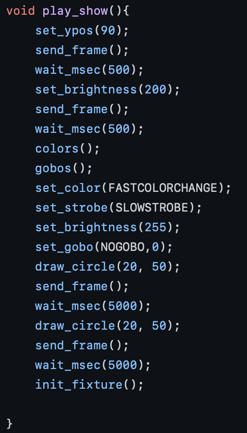
Code Snippet for Example Show
Results
The final result of this project is a reliable working light controller that can be programmed by users. To increase the programmability of the lights, we created a library that allows users to design their own shows without knowledge of the underlying protocols or hardware. We had initially planned on using the touchscreen on the piTFT as a way to control the lights. However, after becoming more familiar with the abundant features of the stage lights, we decided a small touchscreen interface would provide the user insufficient control over the device. As an alternative to this, we created a skeleton program that allows users to create shows by simply adding the commands they want to send to the light, minimizing the amount of programming required. Creating a program has the added benefit of portability, allowing users to create multiple shows in advance and play them on demand.
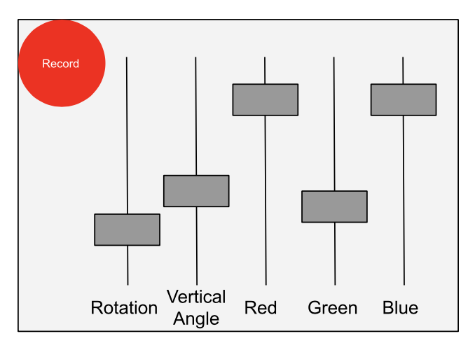
Initially Proposed TFT Display
Conclusion
During this project, we were able to achieve our initial goal of controlling a stage light using a Raspberry Pi microcontroller. The main issue we encountered during the design process was the reliability of communication to the light, resulting from slight inconsistencies in the timing of when pin values were changed. After many attempts to resolve this issue, including using the PreemptRT kernel patch, giving the process a higher priority and running the process on an isolated core, our final solution of using hardware PWM has resulted in a highly robust system we have yet to see fail. We plan on using this design to control light shows at concerts, replacing the need for an expensive and cumbersome light control board.
Future Work
We added some functionality for waiting musical intervals, like measures or beats. However, these functions have not been working with the accuracy necessary to be used in the shows. It is very easy to imagine fixing these functions to enable a more logical animation scheduling mechanism for someone who is musically inclined. Another potential idea is to create a function that would save scenes or full animations. This would allow the user to set up a scene one time and call it at the correct moment. This might make the program even easier to write.
Parts List:
- Raspberry Pi 4B - N/A
- Adafruit PiTFT - N/A
- XLR cable - $15
- 2 BeTopper LS10s - $74.99 each
- USB to XLR cable - $16.99
Code Appendix
// =================================== // dmx.h // =================================== // header file for DMX library // Authors: Kyle Infantino and Jack Brzozowski // Date: 11/9/2022 #ifndef DMX_H #define DMX_H #include <pigpio.h> #include <stdio.h> #include <time.h> #define BILLION 1e9 // Pins and Timing #define D_PLUS 5 #define D_MINUS 19 #define IDLE 1 // The Total Number of Channels to send in the DMX Frame #define NUM_SLOTS 9 // colors #define NOCOLOR 0 #define WHITE 5 #define RED 10 #define GREEN 20 #define BLUE 30 #define YELLOW 40 #define ORANGE 50 #define LIGHTBLUE 60 #define PINK 70 #define PINKLIGHTBLUE 80 #define LIGHTBLUEORANGE 90 #define ORANGEYELLOW 100 #define YELLOWBLUE 110 #define BLUEGREEN 120 #define GREENRED 130 #define AUTOCOLORCHANGE 140 #define FASTCOLORCHANGE 150 // gobos #define NOGOBO 0 #define TRICIRCLE 8 #define SPOTTEDTUNNEL 16 #define MICKEYMOUSE 24 #define TETRIS 32 #define POLKADOTS 40 #define SWIRL 48 #define STRIPES 56 //strobe speed #define NOSTROBE 0 #define SLOWSTROBE 50 #define MEDIUMSTROBE 100 #define FASTSTROBE 200 //rotate speed #define SLOWESTROTATE 0 #define SLOWROTATE 25 #define MEDIUMROTATE 60 #define FASTROTATE 255 extern int send_array[NUM_SLOTS]; extern struct timespec last_frame; // The time at which the last frame ran extern struct timespec elig_time; // The time where frames are eligible to run // setter functions void init_fixture(); void set_position(int x, int y); void set_xpos(int x); void set_ypos(int y); void set_color(int color); void set_gobo(int gobo, int wobble_speed); void set_strobe(int speed); void set_brightness(int brightness); void set_rotation_speed(int speed); void reset_fixtures(); // helpers void write(int LogicalValue); void wait(int micro_seconds); void wait_msec(unsigned long long milliseconds); void wait_sec(int seconds); void wait_beats(int bpm, int beats); void wait_measures(int bpm, int measures, int ts_top); // Drawing void draw_line(int start_x, int start_y, int end_x, int end_y, int speed); void draw_wall_circle(int center_x, int center_y, int radius_degrees, int speed); void draw_circle(int radius_degrees, int speed); // Function to actually send a DMX512 frame void send_frame(); #endif /* =================================== dmx.c =================================== DMX library Authors: Kyle Infantino and Jack Brzozowski Date: 11/9/2022 */ #include "dmx.h" void init_fixture(){ for(int i = 0; i< NUM_SLOTS; i++){ send_array[i] = 0; } send_frame(); wait_sec(1); } // x and y in degrees void set_position(int x, int y){ send_array[0] = (int)x*0.472223; send_array[1] = (int)((y+10)*1.275); } // x in degrees void set_xpos(int x){ send_array[0] = (int)x*0.472223; } // y in degrees void set_ypos(int y){ send_array[1] = (int)((y+10)*1.275); } void set_color(int color){ send_array[2] = color; } // Wobble Speed should be 0-8, where 0 is no wobble, 8 is max wobble void set_gobo(int gobo, int wobble_speed){ send_array[3] = (wobble_speed == 0) ? gobo : gobo+63+wobble_speed; } void set_strobe(int strobe){ send_array[4] = strobe; } void set_brightness(int brightness){ send_array[5] = brightness; } // speed=0 is the slowest, 255 is fastest void set_rotation_speed(int speed){ send_array[6] = 255-speed; } // Puts the light fixture into reset void reset_fixtures(){ send_array[8] = 250; } void write(int LogicalValue){ gpioWrite(D_PLUS, LogicalValue ^ 1); gpioWrite(D_MINUS, LogicalValue); } void wait(int micro_seconds){ int interval = 171 * micro_seconds; for (int i=0 ; i<interval ; ++i ) { /// use delay loop to control frequency // interval 750 = about 4 us } } void wait_msec(unsigned long long milliseconds){ elig_time.tv_sec = last_frame.tv_sec + milliseconds/1000; elig_time.tv_nsec = last_frame.tv_nsec + (milliseconds%1000)*1000000; while (elig_time.tv_nsec >= BILLION) { // This accounts for 1 sec rollover elig_time.tv_nsec -= BILLION; elig_time.tv_sec++; } } void wait_sec(int seconds){ elig_time.tv_sec = last_frame.tv_sec + seconds; } void wait_beats(int bpm, int beats){ unsigned long long msecs = (beats*60000 / bpm); wait_msec(msecs); } void wait_measures(int bpm, int measures, int ts_top){ int beats = measures*ts_top; wait_beats(bpm, beats); } void draw_line(int start_x, int start_y, int end_x, int end_y, int speed){ set_position(start_x, start_y); set_rotation_speed(255); set_brightness(0); send_frame(); wait_sec(1); //wait for light to get where it needs to be set_brightness(10); //Change this set_position(end_x, end_y); set_rotation_speed(speed); send_frame(); } void draw_wall_circle(int center_x, int center_y, int radius_degrees, int speed){ if ( center_x + radius_degrees > 540 || center_x - radius_degrees < 0){ return; } else if ( center_y + radius_degrees > 190 || center_y - radius_degrees < -10){ return; } int waittime; if (speed == SLOWROTATE){ waittime = 5000000; } else if (speed == SLOWESTROTATE){ waittime = 7000000; } else if (speed == MEDIUMROTATE){ waittime = 800000; } else if (speed == FASTROTATE){ waittime = 1000000; } set_position(center_x, center_y-radius_degrees); set_rotation_speed(255); set_brightness(0); send_frame(); wait_sec(1); //wait for light to get where it needs to be set_brightness(10); //Change this set_position(center_x+radius_degrees, center_y); set_rotation_speed(speed); send_frame(); wait(waittime); set_position(center_x, center_y+radius_degrees); send_frame(); wait(waittime); set_position(center_x-radius_degrees, center_y); send_frame(); wait(waittime); set_position(center_x, center_y-radius_degrees); send_frame(); wait(waittime); } void draw_circle(int radius_degrees, int speed){ set_ypos(90-radius_degrees); set_rotation_speed(255); float angle = send_array[0] * 540 / 255; if (angle > 180 && angle < 360){ set_xpos(0); } send_frame(); if(angle>=360){ set_xpos((int)angle-360); }else{ set_xpos((int)angle+360); } set_rotation_speed(speed); send_frame(); } void send_frame(){ struct timespec curr_time; clock_gettime(CLOCK_MONOTONIC, &curr_time); // Get current time to see if frame can be sent // Busy wait until eligible while (curr_time.tv_sec < elig_time.tv_sec){ clock_gettime(CLOCK_MONOTONIC, &curr_time); // Update current time and wait for eligibility } while(curr_time.tv_sec == elig_time.tv_sec && curr_time.tv_nsec < elig_time.tv_nsec){ clock_gettime(CLOCK_MONOTONIC, &curr_time); } // Once eligible, get timestamp of this frame clock_gettime(CLOCK_MONOTONIC, &last_frame); // Send a frame using DMA. int wave_id; gpioPulse_t pulse[NUM_SLOTS*10+4]; gpioWaveClear(); // clear existing waves // write a zero for 100 us (Break) pulse[0].gpioOn= (1 << D_PLUS); pulse[0].gpioOff = (1 << D_MINUS); pulse[0].usDelay = 100; // MAB (write a 1) pulse[1].gpioOn= (1 << D_MINUS); pulse[1].gpioOff= (1 << D_PLUS); pulse[1].usDelay= 14; // Start Code (9 zeros) pulse[2].gpioOn= (1 << D_PLUS); pulse[2].gpioOff = (1 << D_MINUS); pulse[2].usDelay = 36; // Two Stop Bits pulse[3].gpioOn= (1 << D_MINUS); pulse[3].gpioOff= (1 << D_PLUS); pulse[3].usDelay= 8; // Add Actual slot data for (int i = 0; i < NUM_SLOTS; i++){ //start bit pulse[4+i*10].gpioOn = (1 << D_PLUS); pulse[4+i*10].gpioOff = (1 << D_MINUS); pulse[4+i*10].usDelay = 4; int thisSlot = send_array[i]; for (int j = 0; j < 8; j++){ // data bits if(thisSlot & 0x1){ pulse[5+j+(i*10)].gpioOn= (1 << D_MINUS); pulse[5+j+(i*10)].gpioOff= (1 << D_PLUS); } else { pulse[5+j+(i*10)].gpioOn= (1 << D_PLUS); pulse[5+j+(i*10)].gpioOff = (1 << D_MINUS); } // Send LSB first thisSlot= thisSlot >> 1; // Shift out LSB pulse[5+j+(i*10)].usDelay = 4; } pulse[13+i*10].gpioOn= (1 << D_MINUS); pulse[13+i*10].gpioOff= (1 << D_PLUS); pulse[13+i*10].usDelay= 8; //stop bits } gpioWaveAddGeneric(NUM_SLOTS*10+4, pulse); wave_id = gpioWaveCreate(); gpioWaveTxSend(wave_id, PI_WAVE_MODE_ONE_SHOT); gpioWaveDelete(wave_id); wait(1000); //Wait 1000 us for legality of the DMX protocol } // ========================== // show_skeleton.c // ========================== #include <stdio.h> #include <time.h> #include <stdlib.h> #include <sched.h> #include <string.h> #include <sys/mman.h> #include "dmx.h" #include "show.h" #define MY_PRIORITY (51) /* we use 49 as the PRREMPT_RT use 50 as the priority of kernel tasklets and interrupt handler by default */ #define MAX_SAFE_STACK (8*1024) /* The maximum stack size which is guaranteed safe to access without faulting */ void stack_prefault(void) { unsigned char dummy[MAX_SAFE_STACK]; memset(dummy, 0, MAX_SAFE_STACK); return; } int send_array[NUM_SLOTS]; struct timespec last_frame; struct timespec elig_time; int main (int argc, char** argv) { struct sched_param param; gpioInitialise(); gpioSetMode(D_PLUS, PI_OUTPUT) ; // wiringPi pin 23 = GPIO pin 13 gpioSetMode(D_MINUS, PI_OUTPUT); /* Declare this as a real time task */ param.sched_priority = MY_PRIORITY; if(sched_setscheduler(0, SCHED_FIFO, ¶m) == -1) { perror("sched_setscheduler failed"); exit(-1); } /* Lock memory */ if(mlockall(MCL_CURRENT|MCL_FUTURE) == -1) { perror("mlockall failed"); exit(-2); } /* Pre-fault our stack */ stack_prefault(); // Set up eligible frame time to be now so no frames get stuck clock_gettime(CLOCK_MONOTONIC, &elig_time); clock_gettime(CLOCK_MONOTONIC, &last_frame); // Initialize light init_fixture(); // === Your Code goes here ====================== play_show(); // This should be implemented by <your_show_c_file.c> // ============================================= gpioWaveTxStop(); gpioTerminate(); return 0 ; } // =============== // show.h // =============== void play_show();